
| IMPATT Noise Generator CW & Pulse at W-band, 94 GHz : |
| Operation Frequencies: | 93-95 GHz |
| Output power at 94 GHz is equivalent to: | 1 mWatt |
| Pulse duration : | 500 ns - 6 ms |
| Pulse repetition period, kHz: | 0.3-1.0 |
| Flange | UG387/U |
| Waveguide | WR-10 |
| AC power supply : | 115 V |
Insight Product Co. is proud to unveil a new product - a 94 GHz solid state Noise Generator that can operate in both CW and Pulse modes.
Description of Device
The device consists of two modules, a cable that connects them, and a power cable. The first module (I) contains the power supply (AC 115 V), regime switch mechanism and a generator of a series of pulses. The second module (II) is the noise generator.
Photo 1: Module I - Power Supply
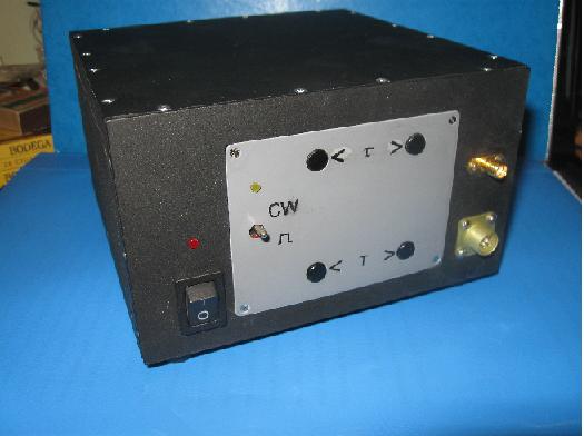
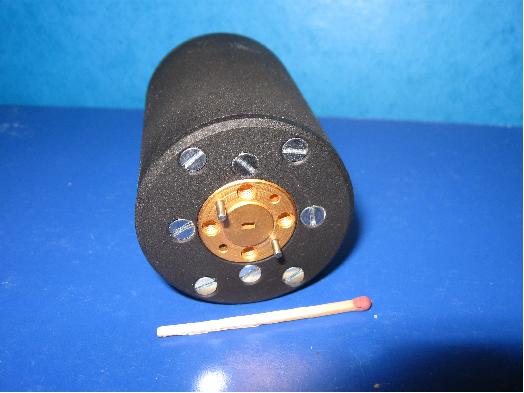
Photo 2: Module 2 - Noise Generator
The front panel of module I has the control switch, buttons and two indicator LEDs. The left part has the ON/OFF switch (I/O) and a LED that if emitting light indicates that the device is ON. In the vertical center of the front panel a up-down switch determines the regime of operation, the up position (CW) corresponds to continuous wave mode, and the down position ( ) corresponds to Pulse mode.
The LED above the regime switch will emit light if the switch is set to the top position, which corresponds to continuous wave (CW) regime. When the device is in pulse regime, you may modify the pulse duration by pressing the top buttons near " τ" symbol on the top part of the front panel ("<" - reduces the pulse duration, ">" - increases the pulse duration). The pulse repetition period can be tuned by pressing the buttons near the "T" symbol on the lower part of the front panel ("<" - reduces the pulse repetition period, ">" - increases the pulse repetition period). Working with these two sets of buttons the user can set the desired pulse train.
Once the power supply is turned on the default pulse duration is the minimum (500 nanoseconds). The monitoring port (SMA) allows the user to control the pulse series. The output resistance of the monitoring port is 50 Ohm. The lower right portion of the front panel has a port for attaching to the cable that connects the two modules. The back panel of module I has an input for attaching the power supply cable and an over-current protector fuse.
The front panel of module II contains a output waveguide flange. The back panel of module II contains an input for attaching the cable that connects the two modules.
Setup procedure
1. Attach the power supply cord to the back panel of module I and plug in the power supply cord into an AC power outlet.
2. Set the ON/OFF switch ("I/O") to be in the lower position ("O") for ON.
3. Set the up-down switch on the front panel of module I to the upper position (continuous wave mode, "CW").
4. Attach the module connector cable to the front panel of module I.
5. Attach the other end of the module connector cable to the input port on the lower right corner of the front panel of module II.
6. Take off the plexiglass protector covering on the waveguide flange by unscrewing two screws.
Conducting measurements
1.Continuous wave operation "CW".
A. Connect the output waveguide flange UG387/U of module II to the measurement device.
B. Turn on Module I.
C. Set the regime switch on the front panel of module I to the top position ("CW")
Notes: The LED above the ON/OFF switch will be emitting light if module I is turned on. The LED above the regime switch will be emitting light if module II is set to continuous wave ("CW") mode.
D. Measure the amplitude of the noise signal.
2. Pulse regime of generation .
A. Attach a coaxial cable to the port for monitoring port (SMA) located on the upper right corner of the front panel on module I.
B. Attach the other end of the coaxial cable to an oscillograph.
C. Set the regime switch to the lower position ( ) corresponding to pulse regime.
D. With the help of buttons near the "τ" symbol ( ">"- increase, and "<"-decrease), set the pulse duration to required level.
E. With the help of buttons near the "T" symbol ( ">"- increase, and "<"-decrease), set the pulse repetition period to required level.
F. By the oscillograph monitor the required level of the pulse repetition rate.
G. Direct the output waveguide flange of module II to the object being studied.
Note:
The radiation pattern of the open waveguide flange has a cardioid shape. The shifts located on the output waveguide do not add any noticeable distortion to the radiation pattern of the output signal.
Warning.
Safeguard the waveguide of module II from other objects and metal particles.
Contact:
| E-mail: | admin@insight-product.com |
| Phone: | (617) 965-8151 |